RISAFloor performs an analysis of columns by taking the individual floor results and using a Modified Hardy-Cross method to distribute moments through the column stack. Here we will talk about some of the details of the RISAFloor column analysis.
Note:
RISAFloor designs a structure in a top to bottom manner, thus following load path. At each floor in the model the loads are brought down and applied to the floor below. This can creates some challenges for column analysis in multi-story applications in certain situations. It may be considered as follows:
Columns that are multi-story that pass through multiple floors will be checked to determine whether an individual floor provides lateral support. A floor will provide lateral support for a column (for both analysis and design) if:
If a beam frames into the column it will brace the column in the direction it is framing in. If a beam frames in that is not in the direction of column local axes then there is different behavior for analysis and design.
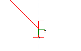
For design considerations the beam will brace the direction it would physically frame into. For example, if a beam frames into a wide flange member the program will check to see if the centerline of the beam hits the flange or the web. If it hits the web it will brace the local y-y direction. If it hits the flange it will brace the z-z direction. A beam that frames in at 45 degrees will brace both column local axes. The example below will brace the y-y direction.
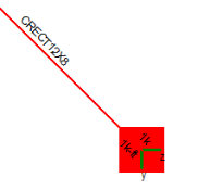
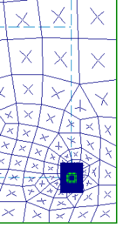
The exception to this occurs if a member frames right at the interface between the strong and weak direction. In that case the program assumes the member is braced only in the z-z direction. See the example below where a concrete beam frames into a square concrete column at a 45 degree angle. In this situation the column is only braced about it's strong axis (z-z) and is not considered braced at this level about it's weak axis (y-y).
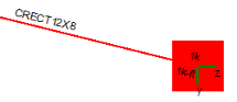
For analysis, if a beam frames in directly along the local axes of the column then the column is only braced in that local axis direction. If a skewed beam frames into a column then it is assumed that the beam braces BOTH local directions, regardless of the angle of the member framing in. In the example below the beam physically frames into the left face of column. However, because it is a skewed member it will be considered to brace the column in both directions for analysis.
For columns with members framing in without eccentricity the column will be an axial-force only element and the analysis is trivial. However, there are several different ways in which moments can be introduced to columns in RISAFloor. Aside from carrying a moment from higher or lower in the column stack, a column can pick up a moment at a floor from the following methods:
|
|
|
|
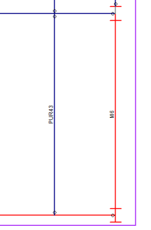
Fixed-End Beams M6 has fixed end releases on either end, which will impart moment forces into the columns accordingly. |
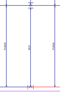
Pinned-End Beams M24 has Column Eccentricity turned on. Thus, there is an eccentricity defined that will impart a moment to the columns based on the reaction * eccentricity. |
Slab Floor (Floor ES only) The slab will be moment connected to the column automatically |
Fixed-end beams can only transfer moment into a column when the Use Column Stiffness checkbox has been checked on the Model Settings.
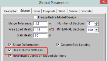
When this is enabled the column's rotational stiffness is approximated for each axis and is considered in the stiffness matrix solution for that floor. Because RISAFloor performs an independent stiffness matrix solution for each floor the column's rotational stiffness is represented (behind the scenes) as a rotational spring boundary condition. This results in some moment redistribution and can therefore affect the amount of moment which the beam carries.
The amount of rotational stiffness provided by the column (rotational spring boundary condition) is influenced by the following factors:
The resultant joint reaction (moment) from the stiffness matrix solution at the spring boundary condition is then distributed to the column. The amount of moment which is sent to the portion of the column above the floor (versus the portion below the floor) is determined using a simplified version of the Hardy Cross Moment Distribution Method.
Note:
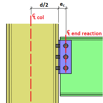
Pinned-end beams can only transfer moment into a column when the Column Eccentricity flag has been checked in the Connections tab of the Beams spreadsheet.
![]()
The moment introduced into the column is calculated using the following formula:
Mcolumn = Rbeam*((dcolumn/2) + econnection)
where
R = Beam end reaction
d = Column depth in the direction which the beam frames into the column (d for strong axis, b for weak axis)
e = Eccentricity between the face of the column and the beam's end reaction resultant
Note:
This feature is only enabled when it has been activated in the Model Settings.
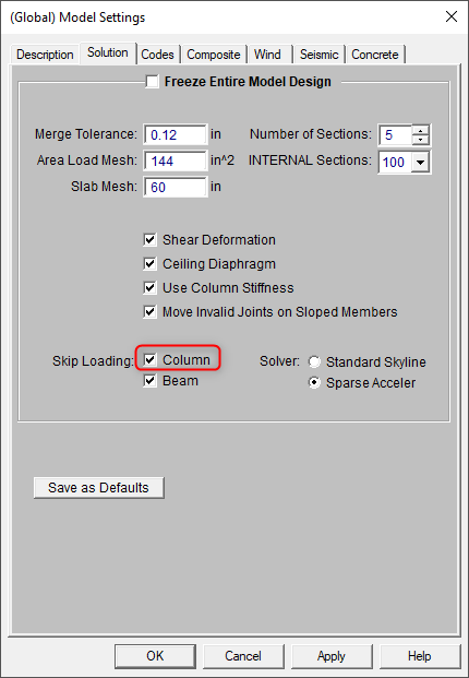
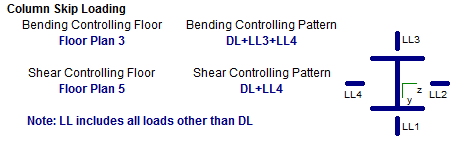
When enabled the program automatically checks for the worst-case unbalanced loading on the columns. The methodology is explained below:
Skip loaded LL moments are carried up and down the column stack by quadrant. The worst case unbalanced load in each quadrant for each floor level is used for hardy cross moment redistribution and for the design.
Note:
Hanger columns can be drawn to support a mezzanine floor. A mezzanine floor is like a typical floor with the only difference being that the floor is supported by hanger columns from the floor above. Therefore, the loads originating from the mezzanine floor will distribute to the hanger columns and then ultimately to the floor above. The hanger column must start from a supporting beam from the floor above and can only support the floor directly beneath. Steps to draw hanger column is presented in To Draw Hanger Columns.
Limitations: